

ADX-24
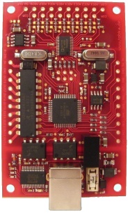
The ADX-24 is an USB-powered 8-channel high resolution analog to digital converter.
It is designed for laboratory applications where high measurement resolution is demanded. A noise free resolution of 20 Bit is possible. This equals 1 million steps.
The board also offers 8 digital inputs and 8 digital outputs for lab automation purposes.
The board is USB-powered. The USB section of the circuit-board is completely isolated from the rest of the board to ensure that overvoltage on the inputs (up to 500 Volts) cannot harm the USB-Port of the computer. Ground loops are also eliminated this way.
All connectors on the board are short-circuit-proof. The digital inputs and outputs are overvoltage-proof to ± 30 Volts. The analog inputs of the A/D-Converter can temporarily withstand ± 20 Volts.
You can order the ADX-24 module here.
Technical Specification
Size: 80 x 50 x 15mm, Weight: 25 grams
USB Connector: USB 2.0 Full Speed
Power supplied over USB
Analog to Digital Converter:
- 24 Bit Resolution
- 8 Channels
- Input Ranges:
- Input Resistance: 1 GΩ (200 KΩ in 10V range)
- Input Bandwidth: 1500 Hz (70 Hz in 10V range)
- Sampling Rate: Up to 500 Samples/Second Selectable Rates: 0.1 , 1 , 2 , 5 , 10 , 62.5 , 125 , 250 , 500 Samples/Second
- Resolution: (in the 2 volt range and with 1 active channel)
- Accuracy: Accuracy without calibration: ±0.1% (±0.2% in 10V range)
- Architecture: Sigma-Delta-ADC (Analog Devices AD7739 with external ADR421 Reference)
-
+/- 0.5 Volt
+/- 1 Volt
+/- 2 Volt (standard)
+/- 10 Volt
If more than 1 channel is active, the maximum sampling rate over all 8 channels together (sum) is still 500 Samples/Second.
An alternative firmware version for 4000 Samples/Second is available upon request and free of charge.
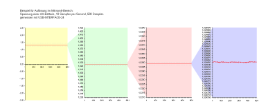
At 1 Samples/s: ±3μV = 20 Bit Peak to Peak = 23 Bit effective (RMS)
At 500 Samples/s: ±10μV = 18 Bit Peak to Peak = 21 Bit effective (RMS)
Demonstration:
(click for larger view)
Accuracy with calibration: ±0.01% (±0.05% in 10V range)
Digital Inputs:
- Perfect for switches, push-buttons and opto-couplers
- Maximum input voltage: ± 30 V
Digital Outputs:
- Perfect for relays and opto-couplers
- Max. current: 400 mA per channel or 800 mA altogether
- External power supply 5 V to 30 V necessary
- Short-circuit-proof and over-temperature-protected
Photo
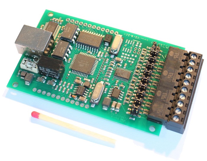
Each of the eight analog inputs can make use of a resistive divider to map a +/-10V input signal to the +/-2V range of the AD7739. The divider is made of precision resistors with 0.1% tolerance and only 25ppm/°K temperature drift.
The pins for the digital IOs are positioned on a 2.54mm grid for standard header rows. Thus the module can be easily mounted on custom circuit boards.
A screw terminal row for the analog inputs is part of the package, but not soldered in as default.
Dimensions:
* incl. 19% Tax excl. Shipping